In late 2003, one of my coworkers (Rick) undertook the challenge of
building an airplane. He selected the Vans RV-10 which is
a 4 place family cruiser with 200mph speed and fixed landing gear. More
information on the aircraft can be found on the Van's
Aircraft RV-10 Webpage. Rick has worked nearly every evening for
almost 2 years straight on the plane. He completed the empennage (tail) and most of the wing ribs by August 2004. From time to
time, I'd stop by and give him a hand riveting on wing skins, fuel tank skins,
and other hard to reach places. Late in the 2004, I started helping more
and more. It's much more fun than
pushing paper at work...
By the end of winter 2004, the wings were complete, the lower fuselage was
complete, and the avionics were going in. I designed the instrument panel
for Rick which took nearly a month by
itself. The panel is fairly impressive with a lot of nice features.
There's a glass cockpit with analog backup. Hookups and a 12" touch
screen for a computer or secondary digital display. The airplane is
equipped for IFR complete with dual GPS, autopilot, satellite radio, DVD
player/laptop personal computer, all electric trim, as well as a full suite of
standard analog instruments (altimeter, compass, airspeed, directional gyro,
artificial horizon, CDI, and vertical speed indicator). Although the panel
is laid out and mostly installed, the long and arduous task of checkout and some
wiring still
must be completed. Checkouts of the panel will probably continue
throughout the next month or so (complete in Feb?).
Below are some photos I took throughout construction. With any luck,
the RV-10 will be flight worthy by Spring 2006. The IO-540 engine and prop
were received in
October. There is still a lot of work to be done before we can install the
engine and roof but we are slowly progressing.
|
|
|
|
|
|
|
|
Blue Mountain EFIS installed facing Aft |
|
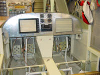
This unit has been modified by BMA to be installed with the connectors oriented aft (different than the standard orientation). The CPU is accessible through panel (removal of LCD screen required). However, removal of CPU requires removal of left side of radio stack supports and 2 of the instruments (VSI, Airspeed). Needed about 1" of clearance more to avoid clearance issue. Maybe on the next one... |
|
|
|
|
|
|
|

|
|
|
|
Center Console Design |
|
Note - Dimensions / Scale Approximations! We used poster board to make actual pattern |
|
|
|
|
|
|
|
|
|
|
|
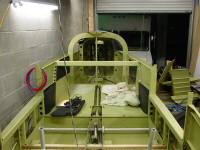
Tail Assembly shortly after joining to forward Fuselage |
|
|
|
|
|
|
|
|
|
|
|
|
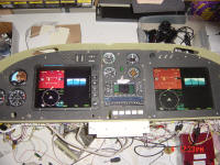
RV-10 Panel Full Power Up First Time |
|
Blue Mountain EFIS up and Running displaying on BMA hi def screen and 600x800 ELO touch screen. |
|
|
|
|
|
|

|
|
|
|
Aft Aux Tray |
|
This is the battery tray, ELT box, and elevator autopilot servo mount which is now attached to the top of the old (modified) battery mount. |
|
|
|
|
|
|
|
|

|
|
|
|
End View of Baggage Light Switch in cross brace |
|
|
|
|
|
|
|
|

|
|
|
|
View of neon tube in cross brace of baggage compartment |
|
|
|
|
|
|
|
|
|

|
|
|
|
Another view of the baggage light neon tube |
|
|
|
|
|
|
|
|

|
|
|
|
Baggage Area Rear Light (Blue) |
|
|
|
|
|
|
|
|

|
|
|
|
Rear Small Baggage Light (Blue) |
|
|
|
|
|
|
|
|
|

|
|
|
|
Another view of the battery tray |
|
|
|
|
|
|
|
|

|
|
|
|
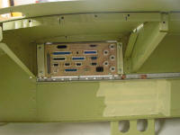
Control Stick junction box |
|
This box contains 3 DB-25 connectors used to connect to each control stick and then run up to the instrument panel. |
|
|
|
|
|
|

|
|
|
|
Close up of the control stick junction box |
|
|
|
|
|
|
|
|
|

|
|
|
|
Defrost Splitter from main heat supply in tunnel |
|
|
|
|
|
|
|
|

|
|
|
|
Defrost control valve assembly and splitter from rear heat duct |
|
|
|
|
|
|
|
|

|
|
|
|
Close up of heater/defrost diverter valve |
|
|
|
|
|
|
|
|
|

|
|
|
|
Pilot Side Exhaust looking up at bottom of panel deck. |
|
|
|
|
|
|
|
|

|
|
|
|
External Power Recepticle in rear baggage area bulkhead near door |
|
|
|
|
|
|
|
|

|
|
|
|
Power connections and solenoid/diode assembly from external power recepticle |
|
|
|
|
|
|
|
|
|

|
|
|
|
Another view of the external power recepticle |
|
|
|
|
|
|
|
|

|
|
|
|
External Power Door Closed |
|
|
|
|
|
|
|
|

|
|
|
|
External Power Door Closed |
|
|
|
|
|
|
|
|
|
|

|
|
|
|
False floor in Tunnel |
|
Raising the fuel pump, filter, and fuel lines 2" off the bottom of the tunnel should add some insulation and mitigate heating problems from hot exhaust flowing under aircraft |
|
|
|
|
|
|

|
|
|
|
Sidewall Insulation |
|
Foil / aircraft inslulation |
|
|
|
|
|
|
|

|
|
|
|
Blue Mountain Magnetometer |
|
No ferrus mounting location in tail - only location in aircraft consistently 24" from any ferrous metal. |
|
|
|
|
|
|

|
|
|
|
Close up of magnetometer mount |
|
|
|
|
|
|
|
|
|
|

|
|
|
|
Parking brake Valve on Firewall |
|
|
|
|
|
|
|
|

|
|
|
|
Pre-Oiler Control Switch |
|
Switch has locking detent requiing operator to pull out to engage. Switch supplies power to oiler and grounds both mags when energized preventing engine firing. |
|
|
|
|
|
|

|
|
|
|
Blue Mountain Power Board |
|
Power board is mounted on co-pilot side of panel behind LCD display. Power board is mounted to 3/8" aircraft grade birch plywood. Plywood is mounted to 3 aluminum channels avoiding and metal to metal contact between power board hardware and aircraft structure. Blue box visible beneath power board is the 24-12V voltage regulator. |
|
|
|
|
|
|
|

|
|
|
|
Power Board View looking Up |
|
View of power board looking up showing bottom of panel (breakers, ELO touch screen, co-pilot defrost) |
|
|
|
|
|
|
|
|
|
|
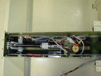
Flap Positioning and Indication System |
|
Bottom Right and Left, you can see the flap position system using a Ray Allen transducer and a arm mounted to the flap torque tube. The Show Planes FPS is installed on the upper left portion of the picture (black box). |
|
|
|
|
|
|
|
|
|
|
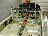
Rats nest #1 - Pre-Wire for the forward fuselage. |
|
|
|
|
|
|
|
|
|
